Stepper Motor Interfacing with 8051: If you’re diving into the world of embedded systems or robotics, one of the essential skills to learn is interfacing a stepper motor with a microcontroller. Stepper motors are widely used in applications where precise position control is needed, such as 3D printers, CNC machines, robotic arms, and automation systems.
In this detailed guide, we’ll walk through everything you need to know about stepper motor interfacing with the 8051 microcontroller, including its working principle, circuit diagram, code, and recommended components. If you’re building your next electronics project or looking for compatible kits, we’ve also included affiliate links to high-quality stepper motor kits, 8051 development boards, and more.
Affiliate Disclaimer: This post contains affiliate links. If you click on these links and make a purchase, we may earn a small commission at no extra cost to you. This helps support our site and allows us to continue providing valuable content. Thank you for your support!
🔧 What is a Stepper Motor?
A stepper motor is an electromechanical device that converts electrical pulses into discrete mechanical movements. Unlike DC motors, stepper motors rotate in fixed angular increments or “steps”, which makes them perfect for precise control.
Types of Stepper Motors:
- Unipolar Stepper Motor: Has a center tap on each winding and is easier to drive.
- Bipolar Stepper Motor: Does not have a center tap and requires a more complex driving circuit.
For this tutorial, we’ll focus on the unipolar stepper motor, which is more beginner-friendly and easier to interface with the 8051 microcontroller.
🧠 Why Use 8051 Microcontroller for Interfacing?
The 8051 microcontroller, developed by Intel, is a classic microcontroller still widely taught in engineering programs and used in DIY electronics. With its simple architecture, it’s an excellent choice for learning hardware interfacing techniques.
The 8051 has multiple GPIO (General Purpose Input Output) pins that can be used to send control signals to a stepper motor driver.
✅ Recommended Product: Buy AT89S52 8051 Development Board on Amazon (Affiliate Link)
- Simplest Arduino Code to Use the Stepper Motor
- What is the primary use of stepper motor?
- Why stepper motor is used in robotics?
- What are real life examples of stepper motor?
- What appliances use stepper motors?
⚙️ How Does Stepper Motor Interfacing Work?
To make a stepper motor rotate, we need to energize its coils in a specific sequence. This sequence causes the rotor to align with the magnetic field, resulting in stepwise movement.
Stepper Motor Drive Modes:
- Wave Drive (One phase ON)
- Full Step Drive (Two phases ON)
- Half Step Drive (Alternate one and two phases ON)
The most commonly used sequence for unipolar stepper motors is:
Step 1: 1000
Step 2: 1100
Step 3: 0100
Step 4: 0110
Step 5: 0010
Step 6: 0011
Step 7: 0001
Step 8: 1001
Each bit in the sequence corresponds to one of the four motor control pins.
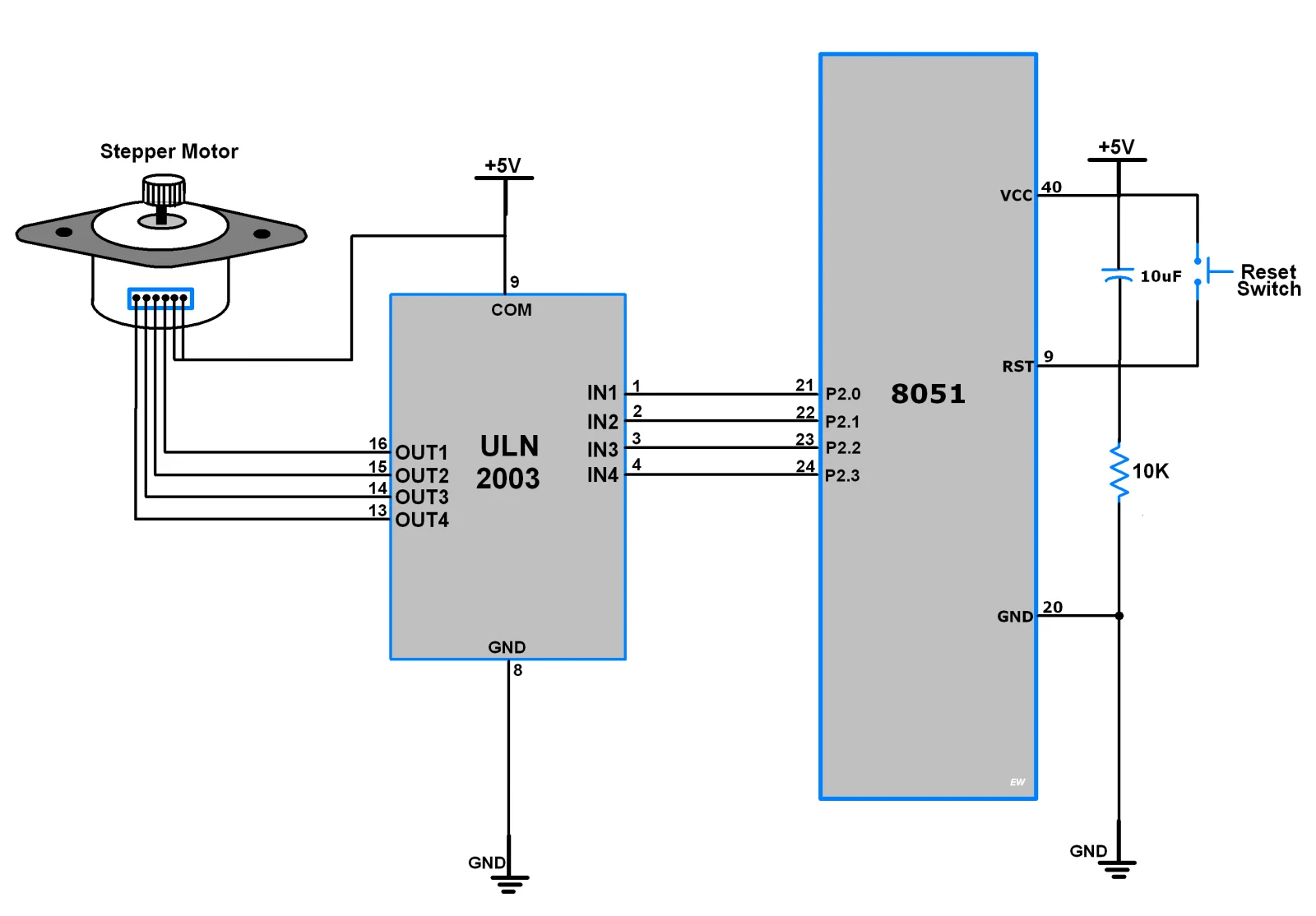
🖥️ Circuit Diagram for Interfacing Stepper Motor with 8051
Here’s what you need:
Components Required:
- AT89S52 or AT89C51 8051 Microcontroller
- ULN2003 or ULN2803 Driver IC
- 5V Unipolar Stepper Motor (28BYJ-48 or similar)
- 12V DC Power Supply
- Resistors, Capacitors, Crystal Oscillator
- Breadboard or PCB
- Jumper Wires
Wiring Overview:
- Connect the stepper motor terminals to ULN2003 outputs (OUT1 to OUT4).
- ULN2003 IN1–IN4 are connected to P2.0 to P2.3 of 8051.
- The common VCC pin of the stepper motor is connected to +12V.
- ULN2003 GND is connected to the circuit ground.

✅ Recommended Kit: Buy ULN2003 Driver + 28BYJ-48 Stepper Motor Module Pack
💻 Stepper Motor Code for 8051 (Keil C)
Here’s a simple code snippet in embedded C using the Keil uVision IDE:
#include <reg51.h>

sbit IN1 = P2^0;
sbit IN2 = P2^1;
sbit IN3 = P2^2;
sbit IN4 = P2^3;

void delay(unsigned int time) {
    unsigned int i, j;
    for(i = 0; i < time; i++)
        for(j = 0; j < 1275; j++);
}

void stepper_clockwise() {
    IN1 = 1; IN2 = 0; IN3 = 0; IN4 = 0;
    delay(10);
    IN1 = 0; IN2 = 1; IN3 = 0; IN4 = 0;
    delay(10);
    IN1 = 0; IN2 = 0; IN3 = 1; IN4 = 0;
    delay(10);
    IN1 = 0; IN2 = 0; IN3 = 0; IN4 = 1;
    delay(10);
}

void main() {
    while(1) {
        stepper_clockwise();
    }
}
You can customize the delay() to control the rotation speed.
⚠️ Precautions and Tips
- Don’t connect a stepper motor directly to the microcontroller — use a driver IC like ULN2003 to handle current.
- Always check the voltage ratings of your motor before powering it.
- Keep an eye on overheating issues if running motors for extended periods.
💡 Project Ideas Using 8051 and Stepper Motor
Here are a few beginner-friendly projects to try:
- Automatic Curtain Opener
- Stepper Motor Position Control Using IR Remote
- Rotating Solar Panel Using LDR and Stepper Motor
- Mini CNC Plotter Using 8051
These projects will help you understand motor control logic while improving your embedded system skills.
✅ Explore More Kits: 8051 Microcontroller + Sensors + Motor Kit for Beginners (Affiliate Link)
📦 Where to Buy Components (Affiliate Links)
Here are some high-quality, budget-friendly kits for your projects:
| Product | Amazon |
|---|---|
| AT89S52 8051 Development Board | Buy on Amazon |
| ULN2003 Driver IC | Buy on Amazon |
| 28BYJ-48 Stepper Motor | Buy on Amazon |
| Complete 8051 + Motor Control Kit | Buy on Amazon |
Using these affiliate links supports our site at no extra cost to you!
📝 Conclusion
Stepper motor interfacing with the 8051 microcontroller is a crucial step for anyone learning embedded systems. With just a few components and some simple code, you can control the movement of motors with high precision. Whether you’re working on robotics, automation, or educational prototypes, this knowledge opens up a world of opportunities.
So why wait? Grab a stepper motor kit, fire up your Keil IDE, and start coding today. Don’t forget to check out our recommended kits to kickstart your journey!
If you found this guide useful, share it with fellow hobbyists and bookmark this page for your future electronics projects. And don’t forget to check out our other tutorials on stepper motor control systems.