Simplest Arduino Code to Use the Stepper Motor: Stepper motors are widely used in 3D printers, CNC machines, robotics, and automation systems. One of the most common ways to control a stepper motor is by using an Arduino and an A4988 stepper motor driver.
In this tutorial, we will learn how to control and change the speed of a stepper motor using the simplest Arduino code. This guide is perfect for beginners who want to understand stepper motor control without complex libraries or advanced programming.
By the end of this article, you will understand:
- How a stepper motor works
- How the A4988 driver controls the motor
- How to change the motor speed using Arduino code
- The complete circuit connections
- Simple Arduino code to run the motor
Understanding Stepper Motors
A stepper motor is a DC motor that rotates in small steps instead of continuous rotation. Each electrical pulse moves the motor by one step, allowing very precise motion control.
This is why stepper motors are commonly used in:
- 3D printers
- CNC machines
- Robotics
- Camera sliders
- Automated positioning systems
Unlike DC motors, stepper motors allow you to control position, speed, and direction accurately.
What is the A4988 Stepper Motor Driver?
The A4988 is a popular driver module used to control bipolar stepper motors. It simplifies the control process so that the microcontroller only needs two pins to run the motor.
These pins are:
STEP pin
Every pulse sent to this pin moves the motor one step.
DIR pin
This pin controls the direction of rotation.
The A4988 driver can operate motors up to 35V and about 2A per coil with proper cooling, making it suitable for many small and medium motors such as NEMA 17.
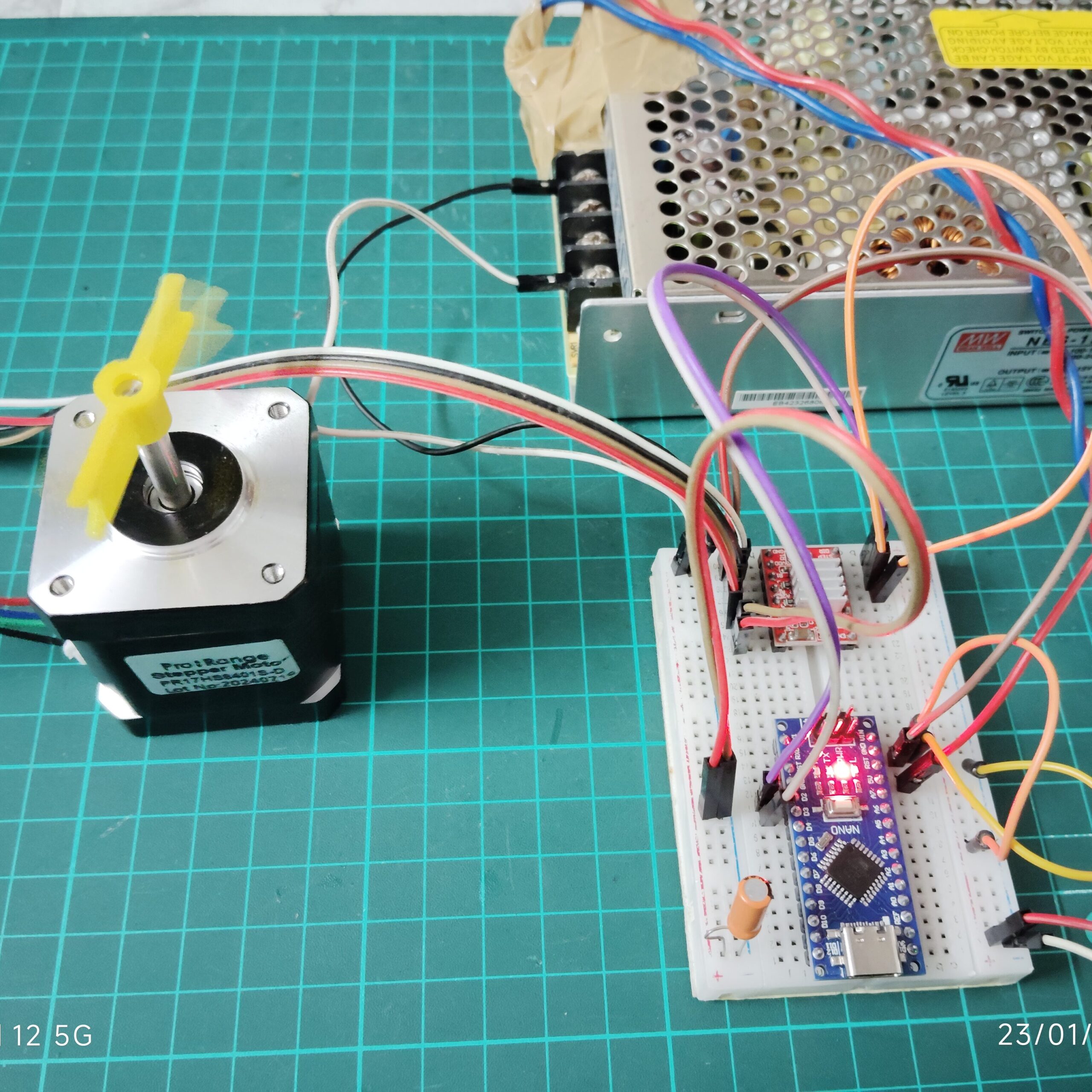
Components Required
To build this simple project, you need the following components:
- Arduino (Uno / Nano / Mega)
- A4988 Stepper Motor Driver
- NEMA 17 Stepper Motor
- 12V Power Supply
- Breadboard
- Jumper wires
- 100µF capacitor (recommended for stability)
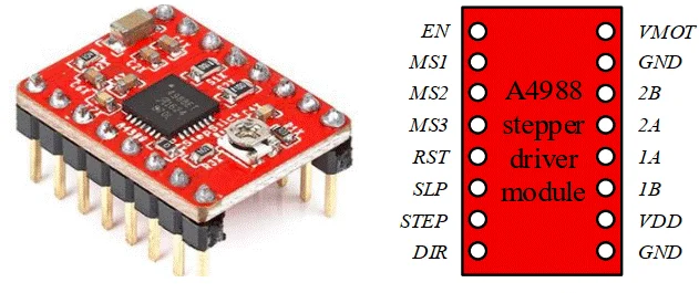
A4988 Pin Overview
Important pins on the A4988 driver:
VDD – Logic power from Arduino (5V)
GND – Ground connection
VMOT – Motor power supply (8V–35V)
STEP – Step signal input
DIR – Direction control
1A, 1B, 2A, 2B – Motor coil connections
The driver internally manages the complex coil switching, allowing the Arduino to control the motor using simple digital pulses.
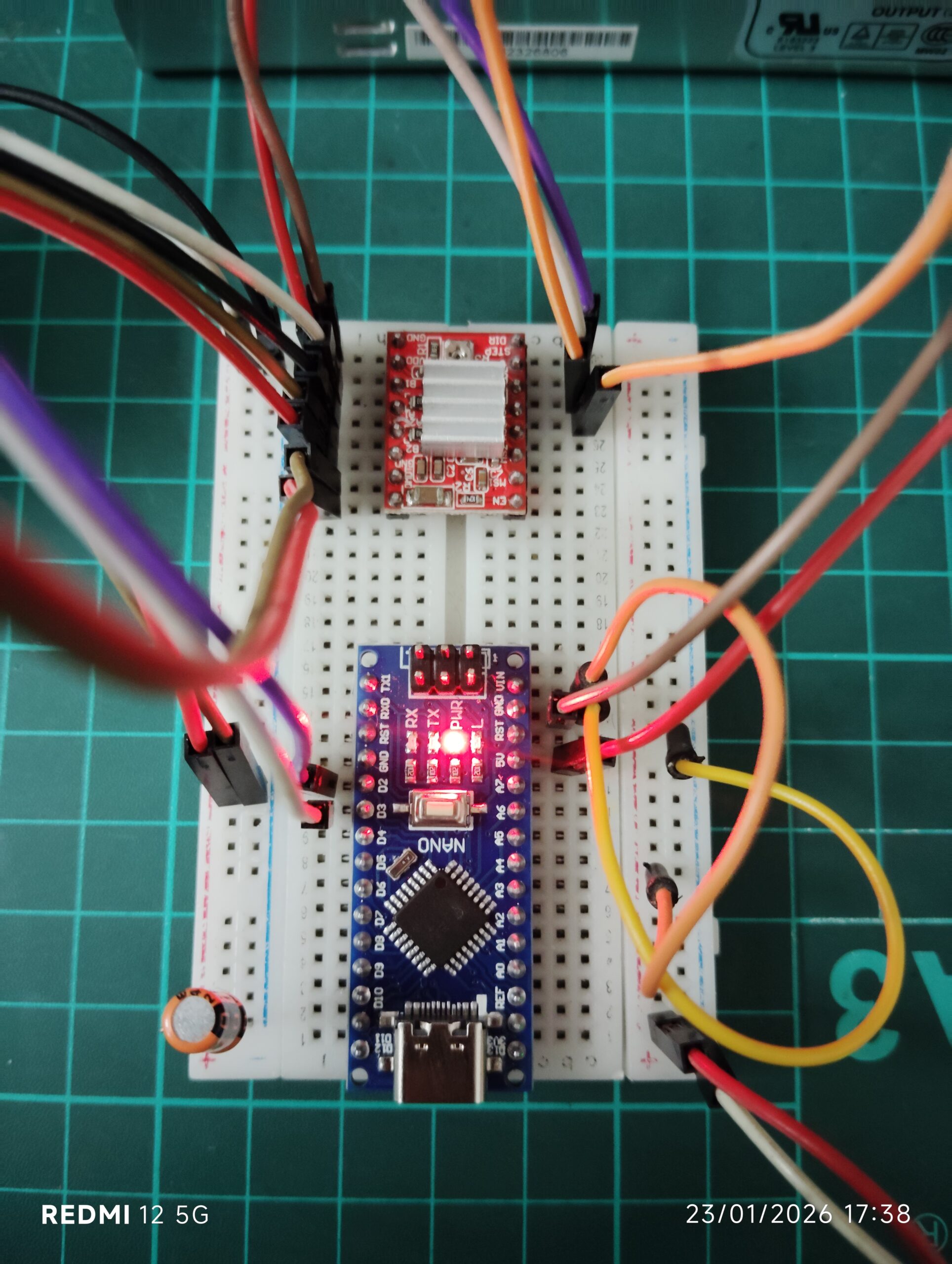
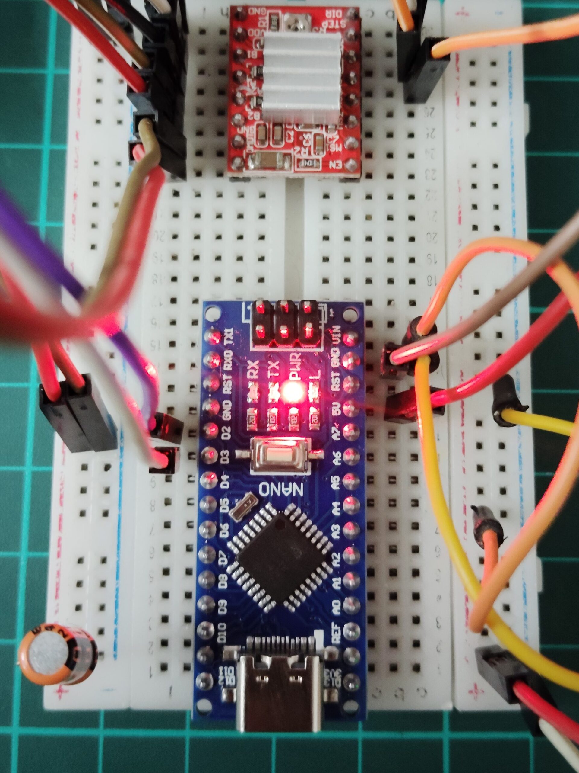
Circuit Connections
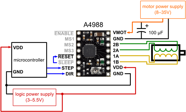
Follow these basic wiring connections.
Arduino → A4988
Arduino Pin 2 → DIR
Arduino Pin 3 → STEP
5V → VDD
GND → GND
Power Supply
12V → VMOT
GND → GND
Stepper Motor
Connect the motor coils to: 1A, 1B and 2A, 2B
Also place a 100µF capacitor between VMOT and GND to protect the driver from voltage spikes.
Arduino Code (Simplest Stepper Control)
Below is a very simple Arduino code to run the stepper motor.
const int dirPin = 2;
const int stepPin = 3;

void setup() {

  pinMode(stepPin, OUTPUT);
  pinMode(dirPin, OUTPUT);

}

void loop() {

  digitalWrite(dirPin, HIGH);

  digitalWrite(stepPin, HIGH);
  delay(50);

  digitalWrite(stepPin, LOW);
  delay(50);

}
This code rotates the stepper motor continuously.
How Stepper Motor Speed is Controlled
The speed of the motor depends on how fast pulses are sent to the STEP pin.
The delay between HIGH and LOW signals determines the speed.
Example:
Slow speed
delay(50);
Fast speed
delay(10);

Fastest speed
delay(5);
Smaller delay means:
Higher pulse frequency
Higher motor speed
This is the simplest way to control stepper motor speed using Arduino.
Changing Speed Dynamically
You can easily modify the code to experiment with different speeds.
Example:
delay(50);   // slow
delay(10);   // medium
delay(5);    // fast
Arduino code – FAST
const int dirPin = 2;
const int stepPin = 3;

void setup() {

  pinMode(stepPin, OUTPUT);
  pinMode(dirPin, OUTPUT);

}

void loop() {

  digitalWrite(dirPin, HIGH);

  digitalWrite(stepPin, HIGH);
  delay(10);

  digitalWrite(stepPin, LOW);
  delay(10);

}
Arduino code – FASTEST
const int dirPin = 2;
const int stepPin = 3;

void setup() {

  pinMode(stepPin, OUTPUT);
  pinMode(dirPin, OUTPUT);

}

void loop() {

  digitalWrite(dirPin, HIGH);

  digitalWrite(stepPin, HIGH);
  delay(5);

  digitalWrite(stepPin, LOW);
  delay(5);

}
This allows you to find the optimal speed for your motor and project.
Applications of This Method
Using Arduino and the A4988 driver, you can build many useful projects:
3D printer motion systems
CNC machines
DIY robotic arms
Automated feeders
Camera sliders
Linear actuators
This simple control technique is the foundation of many advanced motion control systems.
Common Beginner Mistakes
Not using a capacitor on VMOT
Incorrect motor coil wiring
Setting current too high on the driver
Using insufficient power supply
Always adjust the current limit on the A4988 using the onboard potentiometer to protect your motor.
Conclusion
Controlling a stepper motor using Arduino and the A4988 driver is one of the easiest ways to learn motion control. The biggest advantage of this driver is that it simplifies the control interface. Instead of managing complex coil signals, the Arduino only needs to generate simple step pulses.
By changing just one line of code — the delay between pulses — you can easily adjust the speed of the motor. This makes the system ideal for beginners learning about robotics, automation, and mechatronics.
Frequently Asked Questions (FAQs)
How do you control the speed of a stepper motor using Arduino?
The speed of a stepper motor is controlled by changing the time delay between step pulses sent from the Arduino to the STEP pin of the driver (such as A4988). A shorter delay increases the pulse frequency, which increases the motor speed, while a longer delay decreases the speed.
What does the STEP pin do in the A4988 driver?
The STEP pin controls the movement of the stepper motor. Every pulse sent to this pin moves the motor one step forward or backward depending on the direction set by the DIR pin.
What is the purpose of the DIR pin in the A4988 driver?
The DIR pin determines the direction of rotation of the stepper motor.
HIGH signal → motor rotates in one direction
LOW signal → motor rotates in the opposite direction
Why is a capacitor used with the A4988 driver?
A 100µF capacitor is placed between VMOT and GND to protect the driver from voltage spikes generated by the motor coils. This improves stability and prevents damage to the A4988 driver.
What voltage is required to run a stepper motor with the A4988 driver?
The A4988 driver supports motor supply voltages from 8V to 35V. Most projects using NEMA 17 motors commonly use a 12V power supply.
Can a stepper motor run directly from Arduino without a driver?
No. Stepper motors require higher current than an Arduino pin can supply. A driver like A4988, DRV8825, or TB6600 is necessary to safely control the motor.
How many Arduino pins are required to control a stepper motor using A4988?
Only two Arduino pins are required:
STEP pin → controls motor steps
DIR pin → controls direction
This makes the A4988 driver very efficient for microcontroller-based projects.
Why is my stepper motor vibrating but not rotating?
This usually happens due to:
Incorrect motor coil wiring
Insufficient power supply
Current limit set too low on the driver
Ensure the correct motor wires are connected to 1A, 1B, 2A, and 2B on the A4988 driver.
How can I make the stepper motor rotate faster?
To increase speed:
Reduce the delay between step pulses in the Arduino code
Increase the pulse frequency sent to the STEP pin
However, increasing speed too much may cause the motor to lose steps or stall.
People Also Ask (PAA)
What is the easiest way to control stepper motor speed with Arduino?
The easiest way to control stepper motor speed is by changing the delay between HIGH and LOW signals sent to the STEP pin. Smaller delays increase the pulse frequency and make the motor rotate faster, while larger delays slow the motor down.
Why is my stepper motor not rotating with A4988?
A stepper motor may fail to rotate due to several reasons:
Incorrect coil wiring
Missing motor power supply
Current limit set too low
Wrong driver connections
Insufficient delay timing in the code
Checking these issues usually resolves the problem.
How many steps does a NEMA 17 stepper motor have?
Most NEMA 17 stepper motors have 200 steps per revolution, which means each step rotates the motor by 1.8 degrees. When using microstepping with the A4988 driver, the motor can achieve even finer resolution.
What is microstepping in the A4988 driver?
Microstepping is a feature that allows the stepper motor to move in smaller steps than its normal step size. The A4988 driver supports full step, half step, 1/4 step, 1/8 step, and 1/16 step modes, which improve motion smoothness and precision.