
Stepper Motor Connection: Stepper motors are widely used in CNC machines, 3D printers, and robotics due to their precise position control. To use a stepper motor correctly, it must be connected through a suitable driver and controlled by a microcontroller. This article explains step-by-step how to wire a stepper motor with common drivers and microcontrollers.
Understanding Stepper Motor Connection
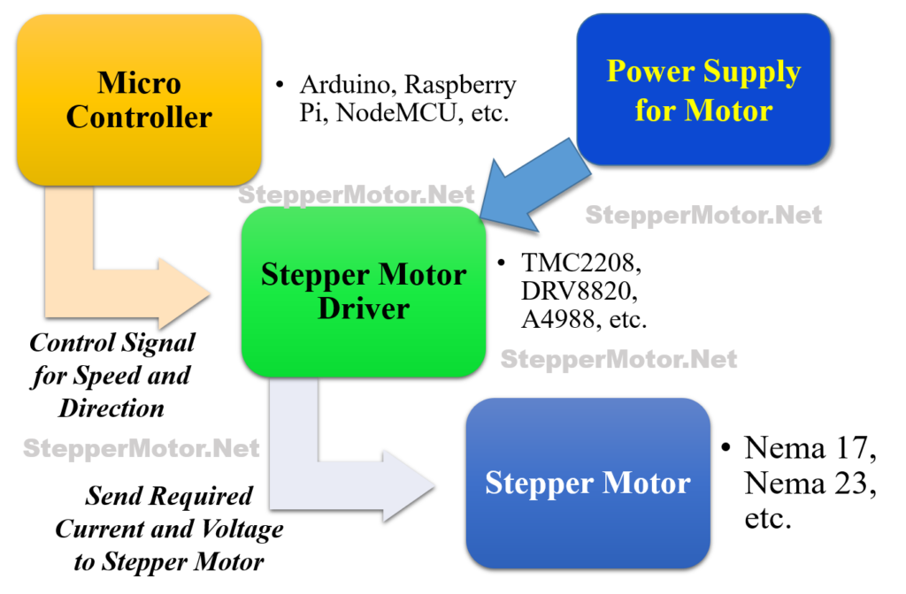
Whenever you are using the stepper motor in your project, you will be needing at least three essential components for execution of your project:
- Stepper motor
- Stepper motor driver
- Pulse generator or a Micro-controller (Like – Arduino, Raspberry Pi, NodeMCU, 8051, etc.)
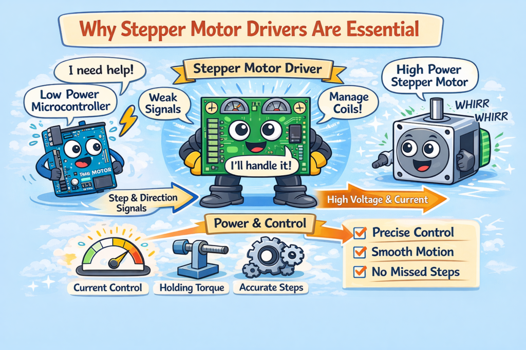
In the case of stepper motors, the stepper driver plays the crucial role, by seamlessly translating the digital commands of microcontrollers into the language of magnetic fields and precise movements.
Can I connect a stepper motor directly to Arduino or any microcontroller?
The short answer for the above question is ‘NO’. ❌
✅ The correct answer is: Use a stepper motor driver. Let’s understand why stepper drivers are essential.
Microcontrollers Cannot Power Stepper Motors Directly
Microcontrollers such as Arduino, ESP32, and Raspberry Pi operate at low voltage levels (3.3V or 5V) and can deliver only a very small amount of current, typically less than 40 mA per I/O pin. This limited power capability is sufficient for sensors and LEDs, but not for driving motors.
In contrast, a stepper motor requires a much higher power supply, usually in the range of 12V to 48V, and draws hundreds of milliamps or even several amps of current to operate correctly.
If a stepper motor is connected directly to a microcontroller:
- The motor may fail to rotate, or
- The microcontroller may overheat or get permanently damaged
To safely bridge this power gap, stepper motor drivers are used.
👉 Stepper motor drivers act as power interfaces, supplying the required voltage and current to the motor while allowing the microcontroller to control motion safely using low-power control signals.
Stepper Motors Need Precise Coil Energizing
Unlike DC motors, stepper motors contain multiple electromagnetic coils and rotate only when these coils are energized in a precise and predefined sequence. This controlled energizing sequence is what allows a stepper motor to move in accurate, fixed steps.
Example of a Typical Coil Energizing Sequence:
- Coil A
- Coil B
- Coil A (reverse polarity)
- Coil B (reverse polarity)
Generating this sequence requires accurate timing, fast switching, and precise current control. Handling such operations directly through a microcontroller is impractical and inefficient, as microcontrollers are not designed to manage high-speed coil switching or current regulation.
This is where stepper motor drivers play a critical role.
Stepper drivers automatically manage the coil energizing sequence, allowing the microcontroller to control the motor using simple digital signals.
| Signal | Purpose |
|---|---|
| STEP | Each pulse moves the motor one step |
| DIR | Sets clockwise or anticlockwise direction |
| ENABLE | Turns motor ON or OFF |
By offloading the complex coil control to the driver, stepper motor drivers make stepper motor operation simple, reliable, and beginner-friendly, while ensuring smooth and accurate motion.
Smooth Motion with Microstepping
Stepper motor drivers play a crucial role in ensuring reliable and efficient stepper motor operation. They precisely control the current supplied to the motor coils, which helps maintain the required holding torque even when the motor is stationary.
By regulating current and switching sequences accurately, stepper drivers also prevent missed steps at higher speeds, ensuring the motor follows the commanded motion without losing position.
As a result, the system achieves accurate positioning, stable and smooth motion, and extended motor life, making stepper drivers essential for applications such as 3D printers, CNC machines, and robotic systems.
How to Select Perfect Stepper Driver
Selecting the ideal driver depends on your project’s needs. Here are some key factors to consider:
- Motor Compatibility: Ensure the driver matches your motor’s type (bipolar, unipolar), voltage, current requirements, and phase configuration.
- Command Interface: Choose a driver compatible with your microcontroller’s communication protocol (e.g., I2C, SPI, PWM) for seamless integration.
- Features and Functionality: Consider additional features like microstepping (for smoother movements), closed-loop control (for precise positioning), and adjustable current levels for optimal performance.
- User-friendliness: Look for drivers with easy-to-use libraries and documentation to simplify setup and programming.
Choosing the right driver isn’t just about technical specifications; it’s about unlocking the full potential of your stepper motor and your project. Here’s how the driver can elevate your creation:
- Enhanced Precision: Smooth microstepping and closed-loop control lead to unmatched positioning accuracy, essential for delicate tasks like robotic surgery or high-resolution 3D printing.
- Increased Efficiency: Optimizing current levels and customizing energizing sequences can significantly improve power consumption, leading to longer battery life for portable devices or reduced energy costs for industrial applications.
- Unleashing Creativity: Advanced driver features like custom programming open doors for innovative applications, from intricate robotic movements mimicking natural gaits to synchronized stepper-powered musical instruments.
- Simplified Development: User-friendly drivers with libraries and documentation streamline setup and programming, allowing you to focus on your project’s core functionality.
- Peace of Mind: Built-in protection mechanisms like current limiting and thermal shutdown provide peace of mind, ensuring your motor and driver operate safely and reliably.
Advance Functions of Stepper Driver
For those seeking the ultimate performance, drivers offer advanced techniques to fine-tune your stepper’s movements:
- Microstepping: Divide each step into even smaller increments for unparalleled smoothness and accuracy, ideal for applications like 3D printing and robotics.
- Closed-Loop Control: Utilize sensors like encoders to monitor the motor’s position in real-time and adjust its movement for unmatched precision, perfect for tasks like CNC machining.
- Current Tuning: Adjust the current levels to each coil for optimal torque and efficiency, maximizing your motor’s performance without overheating.
- Customization: Some advanced drivers allow custom programming of coil energizing sequences for specific applications, opening doors for innovative projects.
Popular Stepper Motor Drivers
Here are some beginner-friendly standalone driver options worth exploring:
- TMC2208/TMC2209: These drivers boast microstepping, sensorless homing, and quiet operation, perfect for 3D printers and CNC machines.
- DRV8820: This powerful driver handles high currents and offers microstepping for smooth movements in robotics and automation projects.
- A4988: The A4988 is a complete microstepping motor driver with built-in translator for easy operation. It is designed to operate bipolar stepper motors in full-, half-, quarter-, eighth-, and sixteenth-step modes, with an output drive capacity of up to 35 V and ±2 A. The A4988 includes a fixed off-time current regulator which has the ability to operate in slow or mixed decay modes.
General Connections of Stepper Driver
While specific connections will vary based on the driver, here’s a general roadmap:
- Power Supply: Similar to Arduino modules, connect separate power supplies for logic and motor, ensuring proper grounding.
- Motor Connections: Follow the driver’s diagram and pin assignments to connect your motor coils to the designated terminals.
- Microcontroller Communication: Drivers often communicate with microcontrollers like Raspberry Pi or ESP32 through protocols like I2C, SPI, or UART. Connect the designated pins on the driver and microcontroller based on the chosen protocol.
- Enable and Direction Pins: Some drivers have additional pins for enabling the motor or controlling its direction. Consult the data sheet for specific connections and configuration options.
Wiring the Stepper Motor
Now you are familiar with stepper motor drivers, lets learn how to integrate the stepper motor with the stepper driver and the micro-controller for proper functioning. Here’s the general flow/procedure for connecting your stepper motor to the driver and microcontroller:
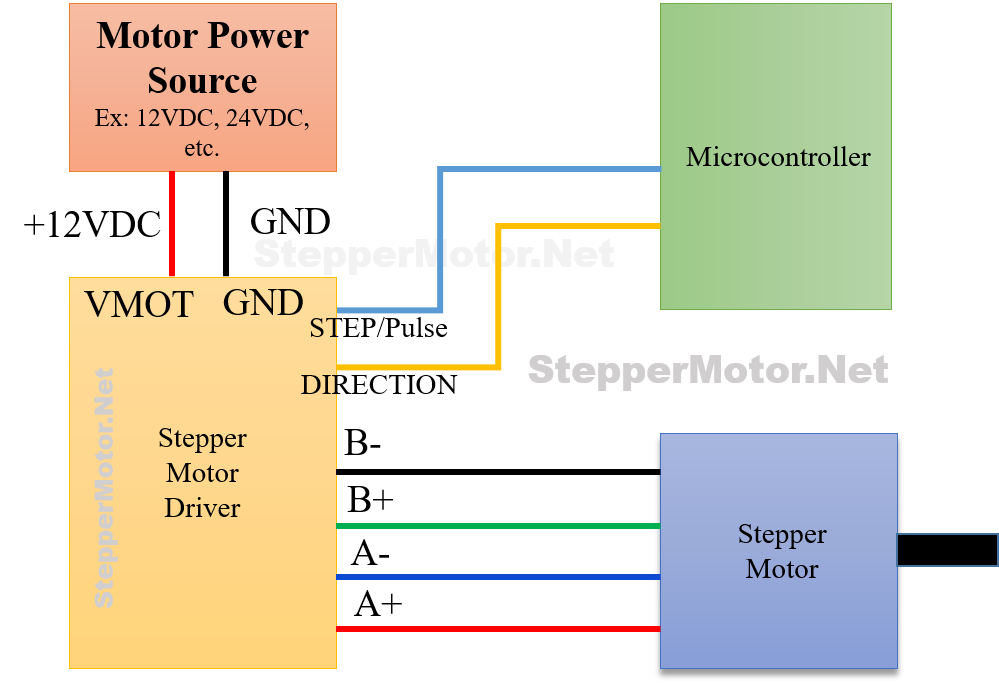
Step 1: Power Supply
- Connect a separate power supply for the driver’s logic circuit (typically 5V) to the designated pins on the driver (e.g., VCC, GND).
- Interface a separate power supply with adequate voltage and current rating for your motor to the designated pins on the driver (e.g., VMOT, GND).
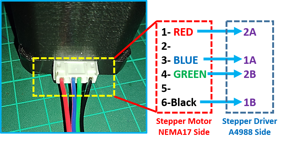
Step 2: Motor Connections
- Identify the motor wires, color-coded if applicable. Consult the motor’s data sheet for specific wire designations (e.g., A1, A2, B1, B2).
- Connect each motor wire to the corresponding terminal on the driver based on the driver’s data sheet and diagram. Ensure correct polarity if your motor is bipolar.
- Double-check your connections with your diagram and data sheet. Use a multi-meter to verify continuity if needed.
Step 3: Microcontroller Communication
- Consult the driver’s data sheet and Arduino library (if applicable) to identify the pins used for communication (e.g., STEP, DIR, ENABLE).
- Connect the designated driver pins for communication to the appropriate digital output pins on your microcontroller.
- Use jumper wires to establish the connections, ensuring clean, secure connections.
Step 4: Additional Settings (Optional)
Some drivers offer additional features like microstepping or direction pins. Consult the data sheet and configure these settings using jumper connections or software commands (e.g., Arduino library functions) based on your desired motor behavior.
Verifying Connection and Function
- Upload your test code (e.g., simple step and direction control program) to your microcontroller.
- Power on the circuit and observe the motor’s behavior. Does it rotate in the intended direction? Is the movement smooth or jerky?
- Adjust settings like step speed and microstepping (if available) using the code or configuration tools to optimize the motor’s performance.
- If the motor doesn’t behave as expected, double-check your connections, verify your code syntax, and refer to the driver’s troubleshooting guide.
Schematics and Diagrams for Different Configurations
Here are some examples of wiring schematics and diagrams for popular driver and motor combinations:
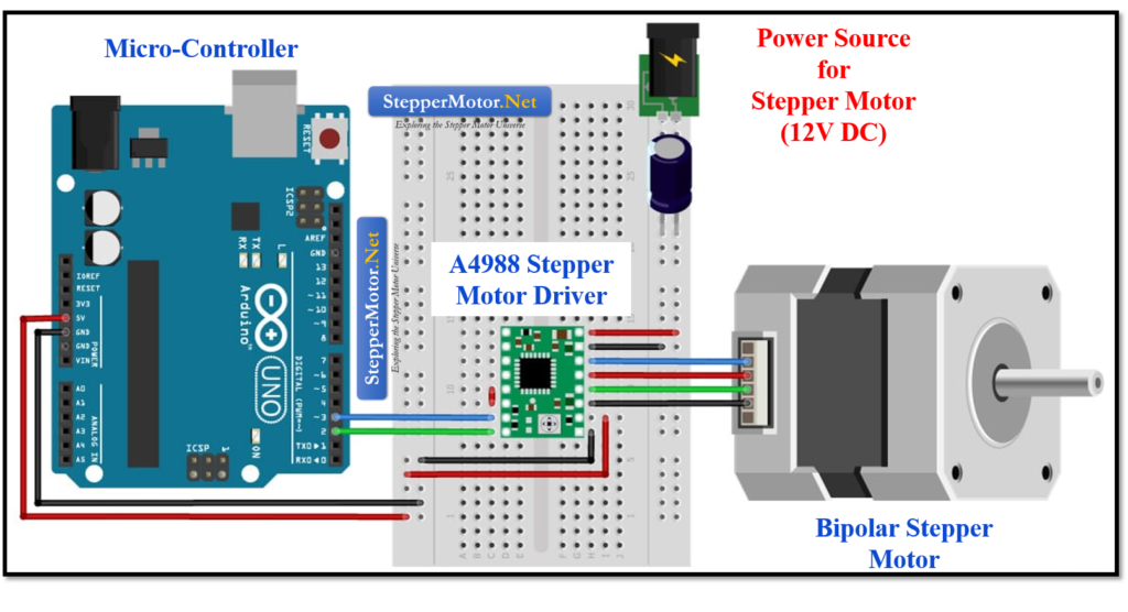
- Arduino UNO + A4988 Driver + Bipolar Stepper Motor: The diagram below shows the interfacing between A4988 driver, Arduino and a bipolar stepper motor connection, power supply connections, and communication pins.
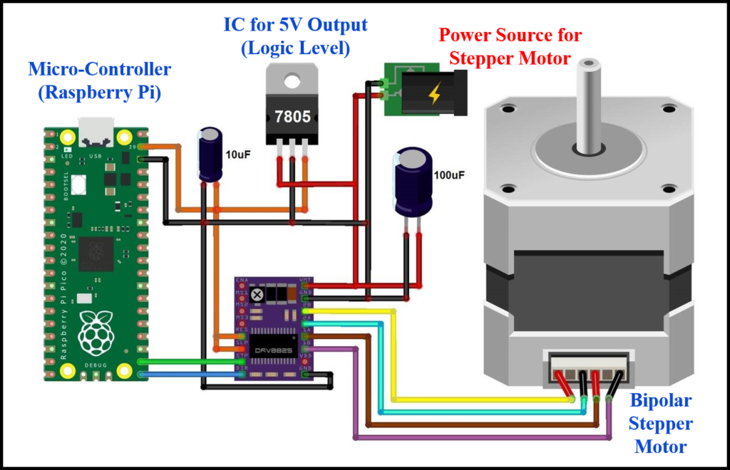
- Raspberry Pi + DRV8825 Driver + Bipolar Stepper Motor: The schematic diagram given below highlighting the power supply connections, motor connections, and communication pins between Raspberry Pi and DRV8825 driver.
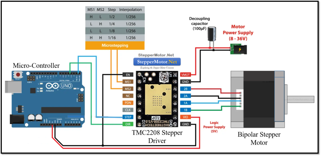
- Standalone Driver (TMC2208) + Bipolar Stepper Motor: The power supply connections, stepper motor connections, and communication pins between Arduino UNO and the TMC 2208 stepper driver has been shown in the figure given below.
Troubleshooting Common Issues
- Motor not rotating: Double-check all connections, verify code syntax, ensure correct power supply voltages, and consult the driver’s troubleshooting guide for specific error codes.
- Stuttering or jerky movement: Adjust the microstepping settings (if available) in your code or driver configuration tools. Check for noise or interference in the power supply or control signals.
- Motor overheating: Ensure your chosen driver and power supply can handle the motor’s current requirements. Consider adding heat sinks for better cooling, especially under high-load conditions.
- Communication errors: Verify the communication protocol used by your driver (e.g., I2C, SPI) and configure your microcontroller code accordingly. Ensure proper grounding and clean connections between the driver and microcontroller.